
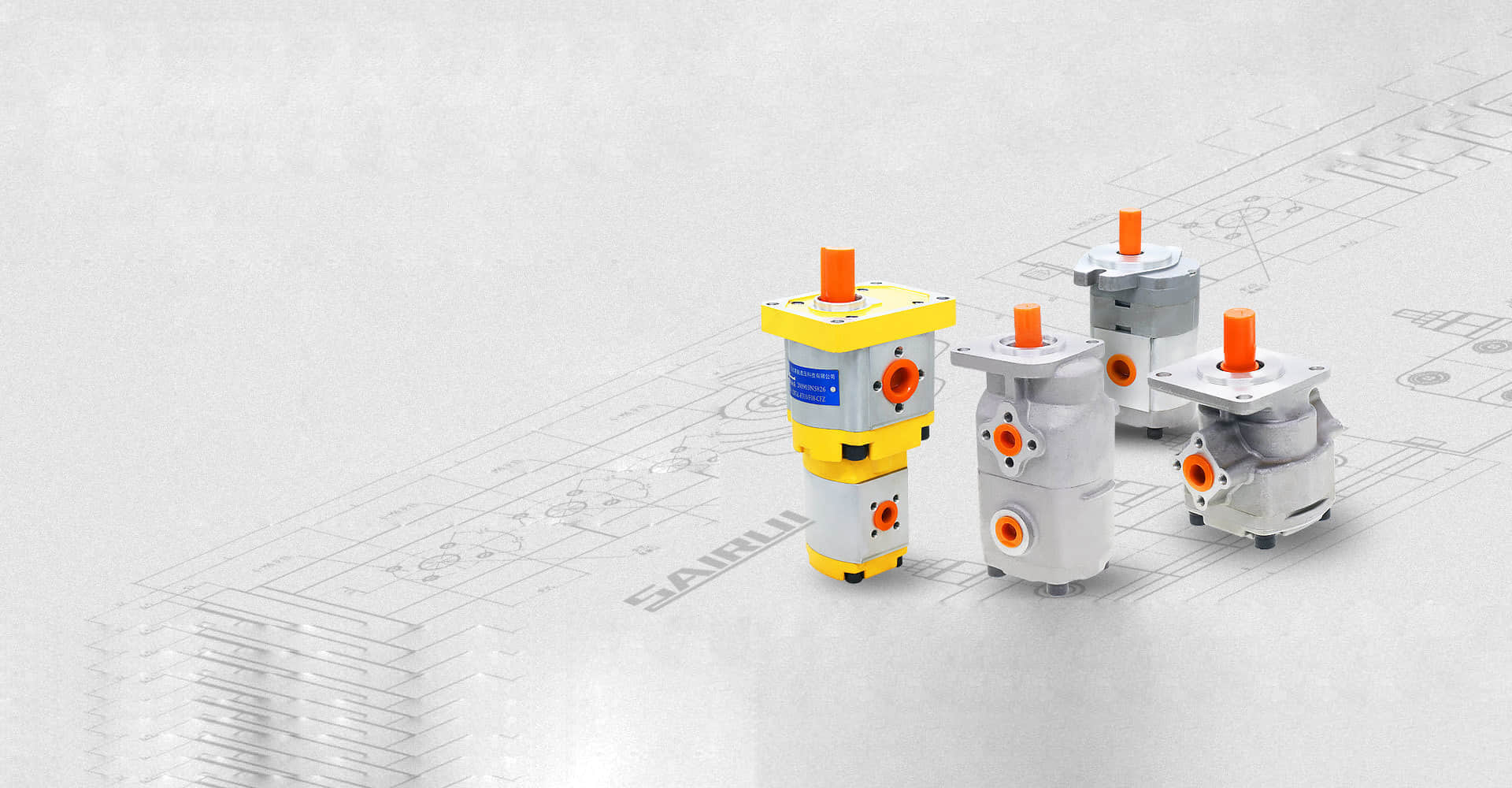
Design and Application of Hydraulic Gear Oil Pump
Considering the actual working condition of the hydraulic gear oil pump, the floating combined shaft sleeve shall be designed to reduce the radial force of the gear pump

Considering the actual working condition of the hydraulic gear oil pump, the floating combined shaft sleeve shall be designed to reduce the radial force of the gear pump, reduce noise and provide axial compensation. The specific design ideas are as follows:
(1) The hydraulic pressing force should be greater than the hydraulic separation force, but it should not be too large. The actual pressing force is 1.2 times the separation force;
(2) The working surfaces of the combined shaft sleeve and gear have unloading grooves at the inlet and outlet directions to avoid oil trapping of the gear pump;
(3) Select a reasonable oil circuit to minimize the radial force on the gear;
(4) The shaft sleeve shall have good lubricity and be able to adapt to thin oil or no oil lubrication conditions.
1. Side panel design:
The side plate can be made of lead bronze and modified polytetrafluoroethylene under limited conditions. The side plate and the combined pump body are connected by a mouth stop.
The radial force of the hydraulic gear oil pump is unbalanced, and the gear shaft deformation deviates to the low pressure area of the pump body, which may lead to scraping and boring. At the same time, the floatability of the shaft sleeve will become worse, and the working life of the bearing will be reduced. When designing the side plate, the method of increasing the high-pressure drainage groove is adopted to increase the range of high-pressure oil area of the gear pump. Only 2 to 3 teeth in front of the pump inlet play a sealing role, so the radial force on the gear is partially balanced, thus reducing the radial imbalance force.
The structure of the external gear pump leads to the oil trapping phenomenon, and the unloading groove on the side plate is a conventional method to reduce the oil trapping phenomenon. On the premise of ensuring that the inlet and outlet are not connected, the trapped oil area will be connected to the pump outlet through the outlet unloading tank when it is reduced, and to the spring inlet through the inlet unloading tank when the trapped oil area is increased. Reasonable design of trapped oil area and unloading groove can greatly improve the working performance of gear pump. There are many specific design methods, which will not be specifically developed here.
2. Practical application:
Because the actual stress of the shaft sleeve of the hydraulic gear oil pump is complex, and the calculation method of the resultant torque is quite cumbersome, here only a design idea is provided to calculate with approximate formula. In the actual design process, we can refer to the above design ideas, and use the CFD simulation method to calculate the stress of the shaft sleeve in detail, which can further increase the design accuracy.